

Fluid Couplings Explained: Types, Working Principle and Selection
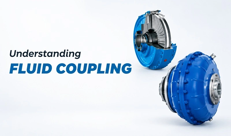
A fluid coupling is a power transmission device that transfers power from a motor to a driven machine through hydraulic fluid. Unlike a mechanical coupling, it does not use direct mechanical contact between the input and output shafts. This helps provide smoother power transmission, reduce the effect of shock loads, and support soft starting of heavy equipment. Variable speed fluid couplings can also adjust the output speed while the motor continues to run at its rated speed.
Premium Transmission is an ISO 9001-certified gearbox manufacturer based in Pune, with more than four decades of experience in manufacturing fluid couplings. Our fluid couplings are used in industries such as mining, cement, steel, power and material handling across India.
What Is a Fluid Coupling?
A fluid coupling is a hydrokinetic device that transfers power through the movement of hydraulic fluid rather than through direct mechanical contact. It is part of the same fluid power transmission family as torque converters. However, unlike a torque converter, a standard fluid coupling does not multiply torque. Instead, it transfers torque with controlled slip, which helps reduce the effect of mechanical shock and protect the drive system from overload conditions.
A fluid coupling is normally installed between an electric motor and the machine it drives. The driven machine could be a gearbox, conveyor, fan, pump or another industrial system. The motor turns the input side of the coupling, while the output side transfers power to the driven equipment. The controlled slip between the input and output allows the coupling to provide a smoother start and helps reduce the impact of sudden changes in load.
Fluid couplings are widely used in heavy-duty industrial applications because their design is relatively simple and reliable. They can help protect the motor and driven equipment during conditions such as sudden load changes, overloads or a jam. Compared with some mechanical soft-starting systems and eddy current couplings, fluid couplings can also offer a low-maintenance method of transmitting power.
Fluid Coupling Working Principle
The operating principle of a fluid coupling is based on the conversion and transfer of kinetic energy through hydraulic fluid, typically turbine oil, circulating between two opposing vaned wheels inside a sealed casing.
The Torque Transfer Process
When the motor starts, it rotates the pump impeller (also called the primary wheel or driving member). The impeller’s vanes throw oil outward by centrifugal force. This oil then flows across the gap and strikes the vanes of the runner wheel (also called the secondary wheel or driven member), which is connected to the load shaft. The impact and circulation of oil on the runner vanes creates a torque that begins to rotate the load.
As motor speed increases, the velocity of the oil circulating from impeller to runner increases. The runner begins to approach motor speed. The difference in speed between the impeller and runner is called slip. At no load the slip is very small, typically under 1 percent. Under full load, slip rises to 2 to 4 % for standard constant fill fluid couplings, which gives a transmission efficiency of 96 to 98 % at rated operating conditions.
If the load jams or stalls completely, the impeller continues to spin while the runner stands still. The oil simply recirculates inside the casing, absorbing the input energy as heat. This prevents the motor from overloading, the motor sees only the hydraulic drag of the coupling, not the stalled load. A fusible plug in the casing melts and releases the oil if the coupling overheats beyond a safe limit, providing a final failsafe.
The Oil Circuit
Inside the working circuit, oil follows a donut-shaped path, outward through the impeller vanes under centrifugal force, across to the runner, inward through the runner vanes toward the centre, and back to the impeller. This self-sustaining circulation continues as long as there is a speed difference between the two wheels. When slip falls to zero, theoretically at no-load simultaneous speed, circulation stops and no torque is transmitted.
This is why a fluid coupling naturally limits starting current: at standstill, the runner is not moving, oil circulation is zero, and transmitted torque starts from zero. Torque builds gradually as oil velocity builds up, giving the smooth, controlled start that protects belts, chains, gearboxes and structures from mechanical shock.
Key Components of a Fluid Coupling
| Component | Function | Notes |
| Pump Impeller (Primary Wheel) | Connected to motor shaft; throws oil outward by centrifugal force | Precision-machined vaned wheel; hardened for long service life |
| Runner (Secondary Wheel) | Connected to load shaft; receives oil energy and transmits torque to load | Matching geometry to impeller; vanes designed for efficient energy capture |
| Working Oil Circuit | Carries kinetic energy from impeller to runner via circulating oil | Turbine oil, grade specified by coupling size and operating temperature |
| Rotating Casing / Shell | Encloses the working circuit; rotates with impeller | Sealed to prevent oil leakage; contains the working oil volume |
| Fusible Plug (Thermal Safety) | Releases oil if casing temperature exceeds safe limit during prolonged slip | Passive thermal protection, no electronics required |
| Scoop Tube (Variable Speed Only) | Adjustable tube inside oil reservoir; controls fill level in working circuit | Position determines output speed; driven by actuator or manual control |
| Oil Reservoir (Variable Speed Only) | Stores excess oil outside working circuit when scoop is retracted | Allows speed turndown by reducing active oil volume in coupling |
| Shaft Seals | Prevents oil leakage along input and output shafts | Critical for maintenance-free operation in dusty or wet environments |
Types of Fluid Couplings Manufactured by Premium Transmission
Premium Transmission manufactures two types of fluid couplings at its Shendra, Chh. Sambhajinagar facilities, designed for the full spectrum of industrial drive requirements.
Type 1: Constant Fill Fluid Coupling
In a constant fill fluid coupling, the volume of oil in the working circuit is fixed during assembly and does not change during operation. The coupling delivers a smooth, progressive soft-start and runs at a near-fixed speed ratio once the load is up to speed.
Construction and working: The pump impeller and runner are housed together in a rotating casing that is sealed with the correct oil fill level. The coupling is flanged or keyed to the motor and load shafts. On starting, oil circulation begins as soon as the motor turns. The load accelerates smoothly as the oil velocity, and the transmitted torque, builds up. At full load, 2 to 4 percent slip is maintained permanently, giving 96 to 98 percent efficiency.
The constant fill coupling has no moving internal parts other than the two vaned wheels and the rotating casing. This makes it extremely robust, virtually maintenance-free and suitable for harsh industrial environments including dusty, wet and high-vibration locations.
Typical performance parameters:
| Full-load slip | 2 to 4 percent |
| Transmission efficiency at rated load | 96 to 98 percent |
| Starting current reduction | 30 to 60 percent versus direct-on-line start (load dependent) |
| Speed ratio | Fixed, output speed tracks input speed minus slip |
| Overload protection | Automatic via hydraulic slip, stall torque limited to coupling rating |
| Maintenance requirement | Oil change per manufacturer schedule; no other planned maintenance |
Best suited for: belt conveyors, screw conveyors, crushers, hammer mills, bucket elevators, compressors and all fixed-speed drives where the primary need is smooth starting and overload protection.
Type 2: Variable Speed Fluid Coupling (Scoop Controlled)
A variable speed fluid coupling (also known as a scoop-controlled coupling) adds an adjustable scoop tube to the basic fluid coupling design. The scoop tube projects into a reservoir of oil that surrounds the working circuit. By moving the scoop inward or outward, the operator or control system changes the volume of oil in the active working circuit, which changes the slip and therefore the output speed.
Construction and working: The coupling has the same impeller and runner arrangement as a constant fill unit, but the casing is extended to form an oil reservoir. A scoop tube, mounted on a stationary carrier inside the rotating reservoir, is positioned by a linear actuator connected to a control system (manual handwheel, electric actuator or pneumatic actuator). Moving the scoop inward scoops more oil into the working circuit, increasing the coupling fill level and raising output speed. Moving the scoop outward reduces fill and lowers output speed.
At minimum scoop position, almost all oil is in the reservoir, the working circuit is nearly empty, and the coupling transmits almost zero torque, the output shaft barely rotates even though the motor runs at full speed. At maximum scoop position, the working circuit is fully filled and the coupling behaves like a standard constant fill coupling with 2 to 4 percent slip. The full speed control range is therefore approximately 0% to 97 to 98% of motor speed.
Typical performance parameters:
| Output speed range | 0% to approximately 97-98% of motor input speed |
| Speed control mechanism | Scoop tube position, manual, electric actuator or pneumatic |
| Transmission efficiency at full speed | 96 to 98 percent (same as constant fill at full fill) |
| Energy saving at 80% speed on fans/pumps | Approximately 49 percent reduction in power (fan law: P = N³) |
| Starting torque | Adjustable, low-torque starting possible by starting with scoop retracted |
| Control response time | Moderate, hydraulic system has inherent lag (suitable for process control) |
| Maintenance requirement | Oil change per schedule; scoop actuator and linkage periodic inspection |
Best suited for: forced draft fans, induced draft fans, boiler feed pumps, centrifugal pumps, long-distance conveyors where throughput varies, and any high-power application above 200 kW where speed control and energy saving are priorities.
Explore our Variable Speed Fluid Coupling product range for detailed specifications, power ratings and mounting configurations.
Constant Fill vs Variable Speed Fluid Coupling: At a Glance
| Criterion | Constant Fill | Variable Speed (Scoop) |
| Output speed control | No | Yes, full range 0 to ~98% of input |
| Energy saving potential | Minimal | High, up to 50% on fans and pumps |
| Construction complexity | Simple and robust | More complex, scoop mechanism |
| Applications | Conveyors, crushers, fixed-speed drives | Fans, pumps, variable-load drives |
| Starting torque | Fixed | Controllable, start at near-zero torque |
| Integration with controls | Not required | Electric or pneumatic actuator + PLC |
| Maintenance | Very low | Low, scoop actuator check |
| Relative cost | Lower | Higher, energy savings offset cost |
For a detailed comparison and selection guide, read our article: Variable Speed vs Constant Speed Fluid Coupling: Which one do you need for your industries application.
How to Select a Fluid Coupling: Step-by-Step
Selecting the right fluid coupling requires more than matching motor power. Below are the steps to ensure the correct coupling for your drive:
Step 1: Define the Motor and Load Parameters
- Motor rated power (kW) and rated speed (RPM): the coupling must be sized to the motor output, not just the average load.
- Load type: is it a fan, pump, conveyor, crusher or compressor? Load type determines the starting torque requirement and the service factor.
- Starting frequency: how many starts per hour? Frequent starts generate heat in the coupling and must be accounted for in sizing.
Step 2: Decide Between Constant Fill and Variable Speed
- If the load runs at fixed speed and you need soft-starting and overload protection only, choose Constant Fill.
- If the load speed must vary during operation, or if energy saving through speed turndown is a priority, choose Variable Speed.
For applications where the driven machine needs its speed to change while the motor continues to run at a constant speed, a variable speed fluid coupling can provide smooth and continuous speed control. The actual suitability depends on the motor rating, driven equipment, operating conditions and required speed range, so the coupling should be selected from the application data rather than motor power alone.
Step 3: Consider the Load and Duty Conditions
The coupling should be selected according to the actual load and operating conditions of the machine. The type of driven equipment, starting conditions, operating cycle and load variations all affect the selection.
For example, Premium Transmission’s variable speed fluid couplings are used for applications such as belt conveyors, crushers, ball mills, hammer mills, centrifuges, ID fans, FD fans and boiler feed water pumps. The right coupling size and configuration depend on the requirements of the individual drive.
This is why it is better to review the complete application before choosing a coupling instead of selecting a unit only from the motor nameplate rating.
Step 4: Check the Shaft and Installation Details
Before finalising the coupling, the mechanical arrangement of the drive also needs to be checked. Important details include:
- Input and output shaft dimensions and keyway details
- Available installation space between the motor and driven machine
- Shaft and mounting arrangement
- Installation orientation
- Operating environment and site conditions
Premium Transmission provides variable speed fluid couplings in several configurations for different industrial applications. Sharing the motor and driven-machine details with the technical team helps in selecting a suitable coupling and configuration for the application.
Where Are Fluid Couplings Used?
Fluid couplings are used in industrial drives where smooth power transmission, controlled acceleration or speed control is required. Premium Transmission’s variable speed fluid coupling range is designed for applications across industries such as cement, chemical, steel, power, oil and gas, food and beverage, material handling, and mining.
| Industry | Common Applications | Suitable Fluid Coupling Applications |
| Mining and Material Handling | Belt conveyors, crushers, mills | Variable And Constant speed application-specific configurations |
| Cement | Fans, conveyors, crushers and mills | Variable And Constant speed applications |
| Power | ID fans, FD fans, boiler feed water pumps | Variable And Constant speed applications |
| Steel | Conveyors, mills and other heavy-duty drives | Application-specific fluid coupling solutions |
| Chemical and Process | Pumps and process equipment | Variable And Constant speed applications |
| Food and Beverage | Industrial material and process handling | Application-specific configurations |
| Oil and Gas | Industrial rotating equipment | Application-specific configurations |
Premium Transmission’s current variable speed fluid coupling range includes PST, PSV, PSVS/DPSVS, PTXL and SCR types. Depending on the model, the products are designed for applications such as belt conveyors, crushers, ball mills, hammer mills, centrifuges, fans, pumps, mixers and agitators.
Why Choose Premium Transmission for Fluid Couplings?
Premium Transmission develops power transmission products for industrial applications and offers both variable speed and constant speed fluid couplings as part of its product range. The company operates four ISO 9001-certified manufacturing plants in India and has engineering, manufacturing and testing capabilities for its products.
Some of the factors that support its fluid coupling offering include:
- Wide product range: The variable speed range includes PST, PSV, PSVS/DPSVS, PTXL and SCR configurations for different drive requirements. Constant speed also has a wide variety and range up to 2000 kW to suit various acceleration time requirement of driven load..
- High power capability: The PST range is available for applications up to 11,000 kW, while other models have their own specified power ranges.
- Industrial applications: The couplings are used for equipment such as conveyors, crushers, mills, fans, centrifuges and boiler feed water pumps.
- Engineering and testing facilities: Premium Transmission has in-house engineering capabilities and uses equipment such as dynamic balancing, CMM systems and other inspection and testing equipment as part of its manufacturing and quality processes.
- Manufacturing network: Its manufacturing facilities are located in Chinchwad, Pune, Falta, West Bengal, and Shendra, Chh. Sambhajinagar.
- After-sales support: Premium Transmission also provides service support through Premium Care for gearboxes, geared motors and fluid couplings.
If you are selecting a fluid coupling for a new installation or replacing an existing unit, the motor details, driven-machine information and operating conditions should be reviewed before final selection.
Frequently Asked Questions About Fluid Couplings
What is a fluid coupling?
A fluid coupling is a power transmission device that uses fluid to transfer torque from one shaft to another. The input element is connected to the motor, while the output element is connected to the driven machine. As the input element rotates, the fluid transfers energy to the output element, allowing the driven machine to start and accelerate smoothly.
Because there is no direct mechanical connection between the input and output elements, a fluid coupling can help provide smooth power transmission and protection against shock loads. Premium Transmission lists smooth and progressive acceleration, protection from shock loads and no-load starting among the key features of its fluid coupling range.
What are the types of fluid couplings?
Premium Transmission offers two main categories of fluid couplings: constant speed fluid couplings and variable speed fluid couplings.
A constant speed fluid coupling uses a controlled amount of oil in its working circuit to transmit power smoothly between the motor and driven machine. A variable speed fluid coupling allows the amount of oil circulating in the working circuit to be controlled, which makes it possible to adjust the output speed while the motor continues to run at a constant speed.
How does a fluid coupling work?
A fluid coupling transfers power through the movement of oil between its input and output elements. The motor rotates the input element, which causes the oil to move through the coupling. The moving oil then transfers energy to the output element connected to the driven machine.
In a variable speed fluid coupling, the amount of oil circulating in the working circuit can be controlled. Changing the oil quantity changes the torque transmitted and can also be used to control the output speed. This allows the driven machine to operate at different speeds while the motor can continue running at a constant speed.
What is slip in a fluid coupling?
Slip is the difference between the speed of the input and output elements of a fluid coupling. Since power is transferred through fluid rather than a rigid mechanical connection, the output element does not normally rotate at exactly the same speed as the input element.
The amount of slip depends on the coupling design and operating condition. It is also associated with heat generation within the coupling. For this reason, the actual operating conditions and thermal requirements need to be considered when selecting a fluid coupling.
What is the difference between a fluid coupling and a torque converter?
Both devices use fluid to transmit power, but they are not the same.
A conventional fluid coupling uses two main rotating elements to transfer power through hydraulic fluid. It does not have a stator for torque multiplication. A torque converter, on the other hand, includes an additional stator that changes the flow of fluid and can provide torque multiplication under suitable operating conditions.
Fluid couplings are widely used in industrial power transmission applications where smooth starting, controlled acceleration and power transmission are required. Premium Transmission’s fluid coupling applications include conveyors, crushers, mills, fans, pumps and other industrial equipment.
How do I know which fluid coupling to choose?
The first question is whether the driven machine needs variable output speed.
If the application requires the driven speed to be adjusted while the motor runs at a constant speed, a variable speed fluid coupling may be suitable. If speed variation is not required, a constant speed fluid coupling may be considered.
The selection should also take into account:
- Motor power and speed
- Driven-machine type
- Required output speed
- Starting conditions
- Load characteristics
- Installation arrangement
- Available space
- Operating environment
Premium Transmission’s variable speed fluid coupling range covers different configurations and power requirements. For example, its PST range is specified for power up to 11,000 kW, while the PTXL range covers 410 to 1,950 kW at 1,500 rpm. The correct model still needs to be selected according to the complete application requirements.
Does Premium Transmission supply fluid couplings across India?
Premium Transmission supplies power transmission products to industrial customers in India and international markets. Its product portfolio includes both variable speed and constant speed fluid couplings, along with helical, worm and planetary gearboxes and geared motors.
The company also has a network of branches, regional sales offices and authorised dealers to support customers. For service requirements, Premium Care provides servicing and repair support for gearboxes, geared motors and fluid couplings.
For a fluid coupling requirement, you can share the motor rating, motor speed, driven-machine details and operating conditions with Premium Transmission’s technical team so that the appropriate product can be evaluated for your application.