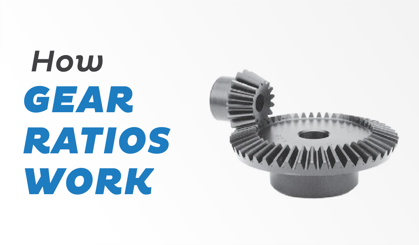
Bevel gears are gears in which the axis of the two shafts overlap, and the gears’ tooth-bearing faces are conical in form. Bevel gears have a cone-shaped pitch surface. Bevel gears are typically installed 90 degrees apart on shafts but may be engineered to operate at various angles.
Bevel Gears – What Are They?
Pitch area and pitch angle are two critical elements in gearing. The pitch area of a gear is the imagined toothless surface obtained by averaging the various teeth’ peaks and valleys. A standard gear’s pitch surface is shaped like a cone A gear’s pitch angle is defined as the angle between the pitch surface’s face and the axis.
The most often encountered types of bevel gears have pitch angles less than 90 degrees and are hence cone-shaped. External bevel gears are so named because their teeth point outward. The pitch surfaces of meshing external bevel gears are coaxial with the gear shafts; the apexes of the two surfaces overlap at the shaft axes’ junction.
Internal bevel gears are beveled gears with pitch angles larger than ninety degrees. They feature teeth that point inward.
Pitch angles of precisely 90 degrees on bevel gears result in teeth that point outward parallel to the axis, like the points on a crown. That is why this particular sort of bevel gear is referred to as crown gear.
The Effectiveness of a Bevel Gear
The effectiveness of a system is defined as the ratio of output to input power. This is distinct from mechanical advantage, which is concerned with amplifying forces or torques via speed sacrifice. When it comes to bevel gears, power loss during transmission is related to friction caused by tooth surfaces moving against one another and stresses applied to the bearings or housing.
The Benefits of a Bevel Gear
Changing the number of teeth (effectively diameter) on each wheel allows for a change in mechanical advantage. By altering the tooth ratio between the drive and driven wheels, one may change the balance of revolutions between them, hence altering the rotational drive and torque of the second wheel in proportion to the first, either increasing speed and lowering torque or decreasing speed and increasing torque.
Bevel Gear Types
Bevel gears are grouped into the following categories according to their geometry:
- Straight bevel gears feature a conical pitch surface and straight teeth that taper to the apex.
- Spiral bevel gears feature curved teeth at an angle, providing progressive and smooth tooth contact.
- Zerol bevel gears are very similar to bevel gears, except their teeth are curved: their ends are parallel to the axis, but their centers are swept circumferentially around the gear. Zerol bevel gears are similar to spiral bevel gears in that they feature curved teeth but have a zero spiral angle, which aligns the teeth’ ends with the axis.
- Hypoid bevel gears are similar to spiral ones but with hyperbolic pitch surfaces rather than conical ones. The pinion may be offset above or below the gear center, allowing for a bigger pinion diameter, increased gear life, and a more seamless mesh. When the beveled surface is parallel to the rotation axis, the arrangement mimics that of a worm drive. In-vehicle rear axles hypoid gears were often utilized.
- Miter bevel gears are a form of bevel gear with a 1:1 gear ratio, which means that both the driver and driven gears have the same number of teeth. This type’s function is restricted to shifting the rotational axis. It generates no mechanical advantage.
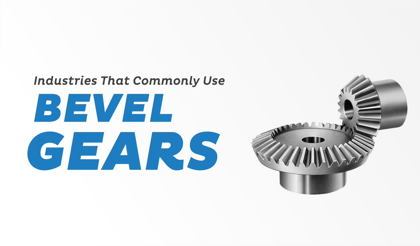
Applications for Bevel Gear
Bevel gears are one of the simplest and most efficient ways to change the rotational axis of a drivetrain. The bevel gear utilization and the application determine the manufacturing and finishing techniques. The following section discusses some of the uses for bevel gear systems.
Automotive
The difference of an automobile is the most standard use of bevel gears. The differential is the component of the front or rear axle assembly that allows for differential rotation of the wheels. This enables the vehicle to turn without sacrificing handling or traction. The driveshaft is attached to the hypoid gear assembly, composed of a pinion and a ring gear. The ring gear is fixed in a planetary gear train and other bevel gears on the carrier.
Hefty Machinery
Heavy machinery uses bevel gears for propulsion, similar to an automobile differential system, or for auxiliary units.
Aviation
Bevel gears are utilized in helicopter power transmission designs, and aircraft auxiliary gearbox operates in the aviation industry.
Equipment for Industrial Plants
Cooling tower fans are indeed an example of bevel gear-driven industrial plant equipment. Typically, the motor is installed on the cooling tower’s deck with the horizontal shaft axis. A gearbox assembly slows speed and improves torque while also vertically reorienting the rotational axis.
Marine
In marine transmission, bevel gears are often employed as part of the stern drive. Two bevel gear sets are used between the engine and the propeller.
Conclusion
There’s no doubt that bevel gears are used across multiple industries and for different applications. However, it’s important to find the right gear for the right application for optimal use. So, if you’re looking for high-quality products, contact our team of experts at Premium Transmission today